Robotics
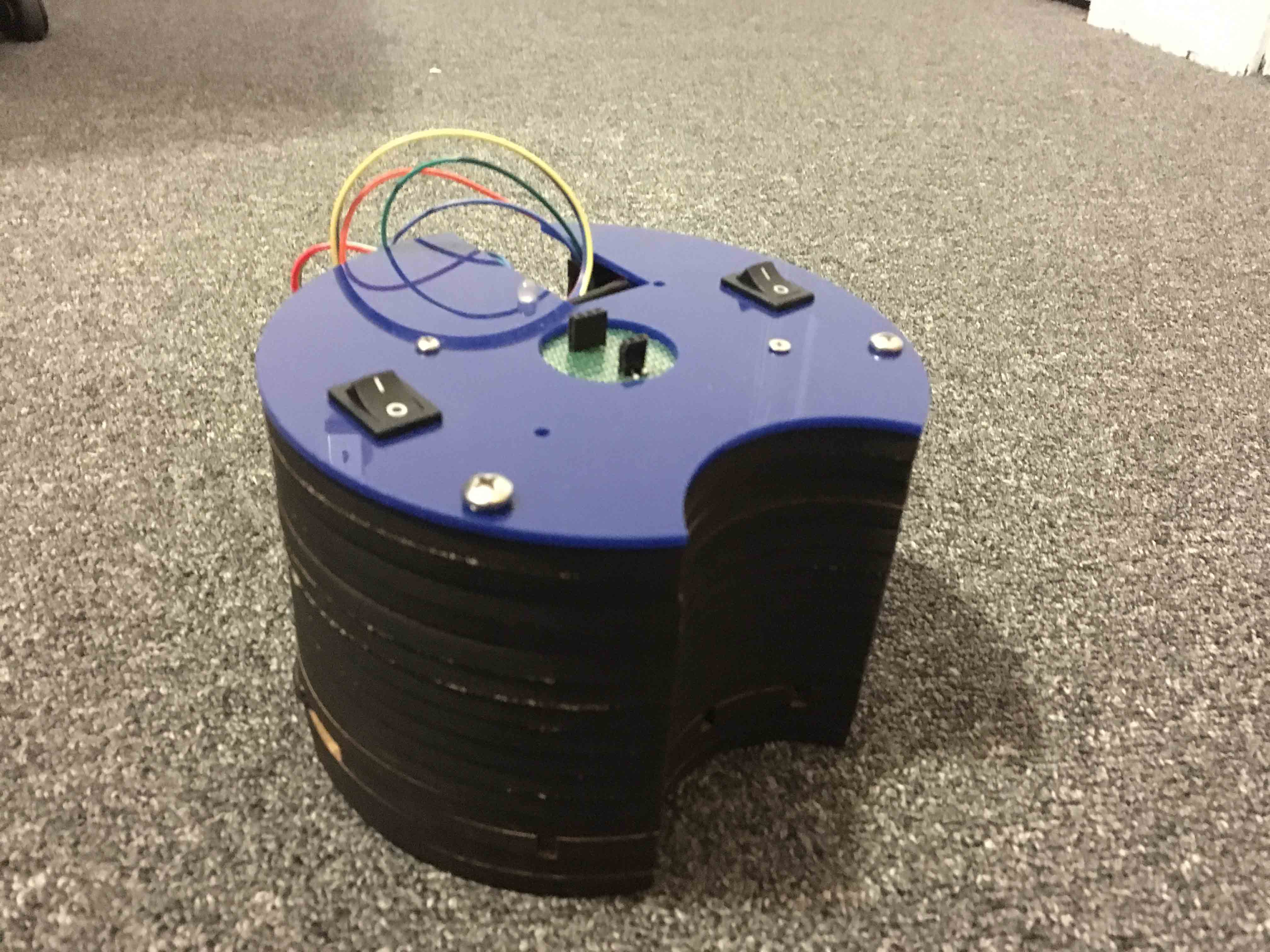
Robockey
Designed, built, and programmed three autonomous hockey playing robots.
Incorporated localization of robot using infrared Wii remote cameras.
Added wireless controls to receive play commands during the game.
The core of this project depended on the robot's localization i.e. know where the robots are on the rink. In order to do this the robots were equipped with IR cameras extracted from Nintendo Wii controllers. The Wii sensor sense 4 brightest IR sources in its field of view. A non-symmetrical IR star pattern was placed such that the mid-point of the pattern coincided with the mid-point of the rink, but separated by a height of about 5 meters. The localization algorithm was coded in way that the robot could calculate its position even with 3 or 2 stars.
Once the robot knew where it was on the rink, it needed to find the puck on the rink. The puck consisted of 8 IR LEDs arranged equally around it. The attacking robots were equipped with 8 phototransitors multiplexed though an analog multiplexer. A simple threshold model was used to determine whether the robot had the puck once it drove to it. The goalkeeper was designed to move either left or right. Once the puck came into the pre-decided proximity of the goalkeeper, the robot moved sideways to prevent the opponent from scoring.
Once the robot knew it had the puck, the algorithm commanded the robot to drive to the goal position depending on which side it was scoring. All robots were equipped with wireless modules to receive game commands.
Localization of a Lost Vehicle using a Particle Filter
Implemented a 2 dimensional particle filter capable of localizing a vehicle within desired accuracy and time.
Localizing algorithm has noisy initial location, sensor and control data.
A two-dimensional particle filter was implemented to help localize a car placed in a relatively unknown location. A less accurate map data (like GPS) was used to initialize the vehicle’s location, after which the new location was predicted based on velocity and yaw rate.
The sensor observation points were transformed into map coordinates, and the observations were associated with landmarks on the map. The likelihood that a given particle made those observations were calculated based off the landmark positions in the map. The particles were then re-sampled based on how likely a given particle was to have made the observations of the landmarks, which further helps to localize the vehicle more accurately. The algorithm was implemented in C++.
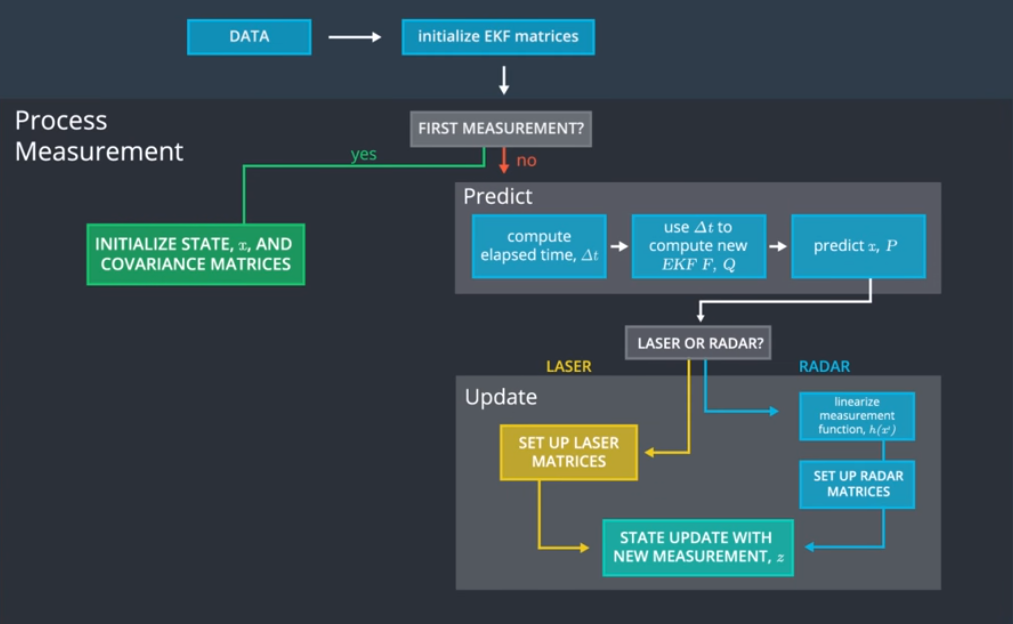
Sensor Fusion using Extended and Unscented Kalman Filter
Implemented constant turn rate and velocity (CTRV) model to detect bicycle moving around vehicle.
Used RADAR and LIDAR measurements of bicycle to determine absolute position.
Calculated root mean squared error with respect to ground truth.
The basic idea of the project was to detect the actual location of a bicycle moving around a vehicle. Simulated RADAR and LIDAR measurements for the bicycle were provided. The data from the two sensors was fused to estimate the exact position of the bicycle.
An Extended Kalman Filter was first implemented on the LIDAR and RADAR data, followed by implementing an Unscented Kalman Filter on the measurements. Further, the root mean square error with respect to the ground truth was calculated as the bicycle moves. The algorithm was implemented using C++ and tested on a Unity simulator which provided the measurements.
Acrobot
Designed, built and programmed a robot to balance on two wheels.
Used a microcontroller, motor driver and an inertial measurement unit.
Implemented a tuned PID control law to make the robot balance on its own.
The robot built was to be fully self-contained, only touch the ground through two coaxially-mounted wheels, and have a center of gravity that is at least one-half wheel radius above the wheel axis. All components were stacked on top of the motor mounting plate.
The robot was equipped with a 9DOF IMU with a 3-axis accelerometer, 3-axis gyroscope, and a 3-axis magnetometer. The idea was to use the IMU to measure how far off the robot is from its equilibrium position. A combination of a digital high pass and low pass filter was coded to combine the accelerometer and gyroscopic data to find the angle at which the robot is from its equilibrium position.
This data was then used as input to a PID control law.
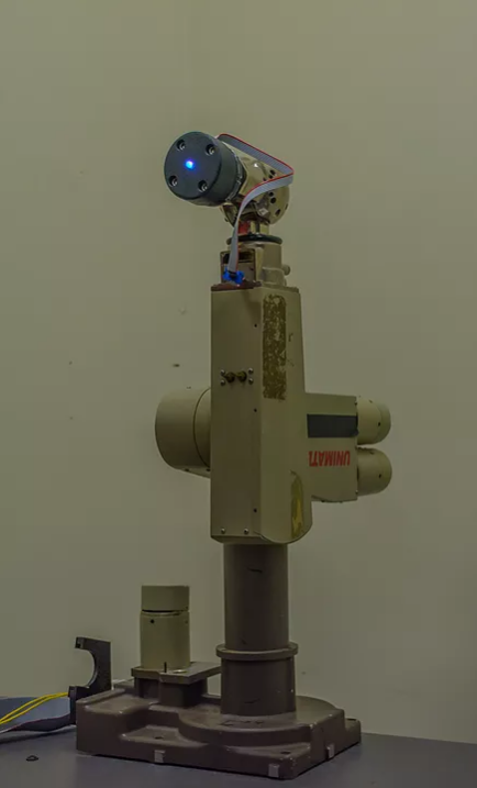
Robotic Arm
Solved and coded complete inverse kinematics for the PUMA 260 robotic arm.
Simulated light painting of a Rubik's cube using the PUMA robot on MATLAB.
Captured painting of Rubik's cube on actual PUMA robotic arm using long exposure photography.
In order to reach a particular point in the reachable workspace, the inverse kinematics for the robot needs to be solved to determine the joint positions and angles it should be at to reach that point. The inverse kinematics for a PUMA 260 robotic arm are solved and coded on MATLAB.
MATLAB code is written to make a PUMA 260 robotic arm draw something interesting in the air with a colored light, which is captured by taking a long-exposure photograph. Drawing precise, arbitrary shapes with the robot requires us to solve the robot's full inverse kinematics. As part of this project, the full inverse kinematics of the robotic arm are solved by hand. The inverse kinematics are further coded on MATLAB. For the purpose of this project, we have chosen a Rubik's cube as the light painting. The MATLAB code is then run to simulate the light painting. Once the painting comes out to what we want it to be, the code is then run on an actual PUMA 260 robotic arm. The LED on the PUMA arm is then used to reproduce the simulation. The light painting is then captured using long exposure photography.
Orchestra
Designed and constructed a battery-powered, GF1004-based instrument capable of playing a tone for a specified duration when requested via a wireless command.
The project dealt with coupling a microcontroller with a wireless module is order to produce sound in our specified frequency range. In order to generate a tone in the tenor range (180-300 Hz), the tone was generated using a sine table to generate a sine wave. This sine wave was later smoothened using a low pass RC filter. Using a transistor, the speaker was connected to produce the sound whenever the wireless signal was sent through the wireless transmitter.
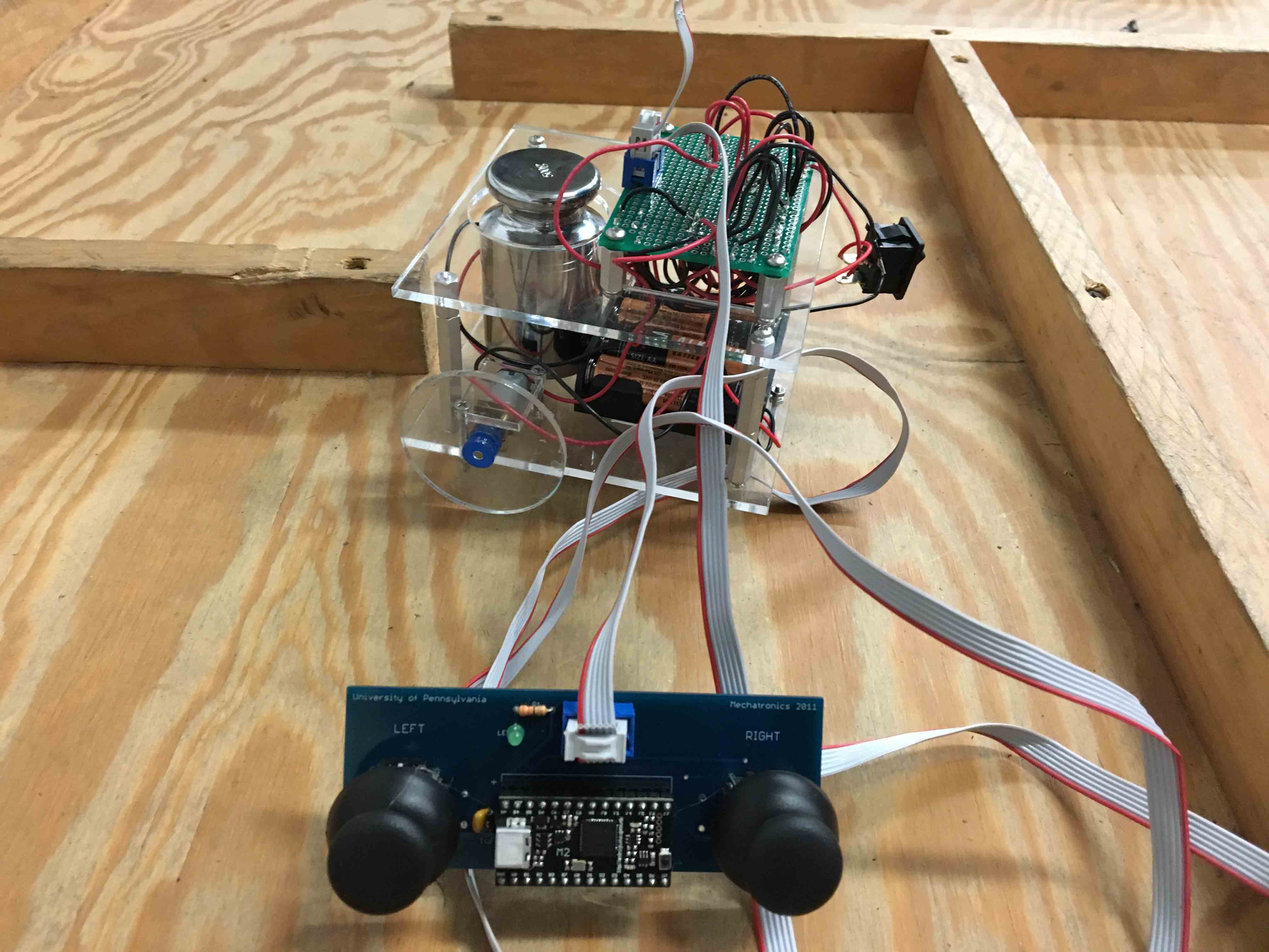
Labyrinth
Built a joystick controlled, maze traversing robot, capable of carrying a 500-gram payload.
The project aimed at building a maze traversing robot using a joystick. The challenge of the project was to build the robot without using any programmable components (such as microcontrollers). Further, the robot had to be able to carry a 500-gram payload. The robot incorporated a motor driver circuit which was built using a quad-half H driver and a hex inverter.
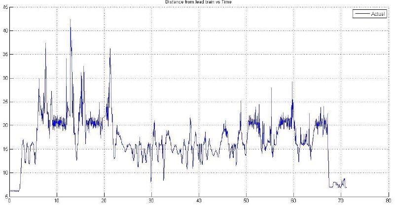
Implementation of Feedback System to Form a Train Chain
Utilized Arduino microcontroller, Ultrasonic Ping and Hall Effect sensors to implement feedback system.
Coded PID control law on Arduino to make train follow lead train at fixed distance.
Uniform traffic flow is a concept that seems oblivious considering factors that contribute to bottlenecking of traffic such as human response. Thus, to implement a chain of vehicles following each other at a fixed distance, the knowledge of control systems can be implemented.
This project is a small step in that direction. Using an ultrasonic ping sensor, a Hall Effect sensor and an Arduino microcontroller, a PID law is coded to make a chain of small trains follow a lead train. The required gains needed for this purpose are calculated using frequency response techniques (Bode plots).